AstroAI Multimeter Manual: A Comprehensive Guide (Updated 04/22/2026)
Greetings and welcome! This comprehensive guide supports your new AstroAI Digital Multimeter‚ offering detailed instructions for optimal use and understanding its features.
Welcome to the world of electrical measurement! The AstroAI Digital Multimeter is a versatile and reliable tool designed for both professional electricians and DIY enthusiasts. This manual serves as your guide to unlocking the full potential of your new multimeter‚ ensuring accurate and safe measurements for a wide range of applications.
This True RMS 6000-count multimeter offers precision and functionality‚ allowing you to confidently tackle electrical projects. Whether you’re working on automotive repairs‚ home electrical systems‚ or general electronic troubleshooting‚ this device provides the necessary features to get the job done right. We’ve designed this manual to be user-friendly‚ providing clear explanations and step-by-step instructions.
Throughout this guide‚ you’ll learn about the multimeter’s various functions‚ safety precautions‚ and troubleshooting tips. We encourage you to read this manual thoroughly before operating the device to maximize its benefits and ensure your safety. Let’s begin your journey to mastering electrical measurement with the AstroAI Multimeter!
What’s in the Box: Unboxing and Component Check
Carefully unpack your AstroAI Multimeter and verify that all components are present and undamaged. Your package should include the following items: the AstroAI Digital Multimeter (True RMS 6000 counts)‚ a pair of test leads (red and black)‚ a 9V battery‚ a thermocouple (for temperature measurements)‚ and this comprehensive user manual.
Inspect each item for any signs of physical damage that may have occurred during shipping. If any components are missing or appear damaged‚ please contact our customer support team immediately for assistance. Before first use‚ ensure the battery is correctly installed in the battery compartment‚ observing the proper polarity (+ and -).
Familiarize yourself with the location of the test lead jacks‚ the display screen‚ and the function selection dial. A quick visual check will help you understand the layout and prepare for accurate measurements. Retain the original packaging for potential future transport or warranty claims.
Safety Precautions and Warnings
Prioritize safety when using your AstroAI Multimeter. Always disconnect power to the circuit under test before making any electrical connections. Never exceed the multimeter’s specified input limits‚ as this could result in damage to the instrument or pose a safety hazard. Use extreme caution when working with high voltages‚ and always wear appropriate personal protective equipment (PPE)‚ including safety glasses and insulated gloves.
Do not use the multimeter in wet or damp environments‚ and avoid touching exposed metal parts while taking measurements. Ensure the test leads are in good condition‚ with no cracks or breaks in the insulation. This multimeter is designed for indoor use only. Improper use can lead to electric shock or injury.
Read and understand this manual completely before operating the device. Keep this manual readily available for future reference and always follow all safety guidelines.

Understanding the Multimeter Display
The LCD screen clearly presents readings with symbols indicating units and measurement mode‚ ensuring accurate interpretation of voltage‚ current‚ resistance‚ and other values.
LCD Display Overview: Symbols and Units

The AstroAI multimeter’s LCD display is designed for clear and concise presentation of measurement data. Understanding the various symbols and units is crucial for accurate readings and safe operation. The primary display area shows the measured value‚ while secondary indicators provide additional information. Key symbols include ‘V’ for Volts (both DC and AC)‚ ‘A’ for Amps (DC and AC)‚ and ‘Ω’ for Ohms‚ representing resistance.
A diode symbol indicates diode testing mode‚ and a capacitor symbol signifies capacitance measurement. The frequency is displayed in Hertz (Hz). Temperature readings are shown in Celsius (°C) or Fahrenheit (°F)‚ depending on the selected setting. A battery symbol alerts you to low battery levels. Other important indicators include ‘AC’ and ‘DC’ to denote the type of current or voltage being measured‚ and ‘HOLD’ when the data hold function is active. Familiarizing yourself with these symbols ensures you correctly interpret the multimeter’s output and avoid misinterpretations.
Backlight Functionality and Adjustment
The AstroAI multimeter features a convenient backlight function to enhance visibility in low-light conditions. Activating the backlight is typically achieved by pressing a dedicated ‘Backlight’ button on the front panel. This illuminates the LCD display‚ making readings easier to discern in dimly lit environments. The backlight’s intensity is often adjustable‚ allowing you to customize the brightness level to suit your preferences and the surrounding lighting.
Some models offer multiple brightness settings‚ selectable through a combination of button presses or a dedicated menu. A brighter backlight consumes more battery power‚ so adjusting it appropriately can help extend battery life. Regularly check the battery level when using the backlight frequently. If the backlight appears dim or flickers‚ it may indicate a low battery or a potential issue with the backlight circuitry. Proper use of the backlight ensures optimal readability and user experience.
Low Battery Indicator and Replacement
The AstroAI multimeter is equipped with a low battery indicator‚ typically represented by a battery symbol on the LCD display. When this symbol appears‚ it signifies that the batteries are nearing depletion and need replacement to ensure accurate measurements. Ignoring this warning can lead to unreliable readings or complete multimeter failure.
To replace the batteries‚ locate the battery compartment‚ usually on the back of the multimeter. It’s often secured with a small screw or a latch. Open the compartment and remove the old batteries‚ noting their polarity (+ and -). Insert new batteries of the correct type (typically AAA or 9V) matching the polarity markings inside the compartment. Ensure the batteries are securely seated before closing the compartment. Always dispose of used batteries responsibly according to local regulations.
Basic Measurement Functions
This section details core functionalities: voltage‚ current‚ and resistance measurements. Learn to accurately assess electrical circuits with these essential‚ foundational techniques.
Voltage Measurement (AC/DC)
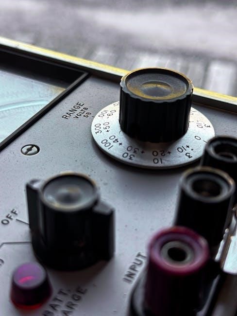
Measuring voltage is fundamental to electrical work‚ and your AstroAI multimeter excels at both AC and DC voltage readings. Begin by selecting the appropriate voltage range on the rotary dial – DC voltage is typically represented by a ‘V’ with a straight line‚ while AC voltage uses a ‘V’ with a sine wave symbol;
Insert the black test lead into the ‘COM’ jack and the red test lead into the ‘V’ jack. To measure DC voltage‚ connect the probes in parallel with the circuit or component you wish to test‚ observing correct polarity (red to positive‚ black to negative). For AC voltage‚ polarity doesn’t matter.
The multimeter will display the voltage value. If the reading is unstable or outside the selected range‚ adjust the range accordingly. Always exercise caution when measuring voltage‚ especially in live circuits‚ and never exceed the multimeter’s maximum voltage rating. Remember to double-check your connections before powering on the circuit.

Current Measurement (AC/DC)
Measuring current requires a series connection within the circuit‚ differing from voltage measurement. Select the appropriate current range on the rotary dial; DC current is indicated by ‘A’ with a straight line‚ and AC current by ‘A’ with a sine wave. Crucially‚ move the red test lead to the ‘A’ jack (often fused – check fuse specifications!).
Break the circuit and insert the multimeter in series – the current must flow through the meter. For DC current‚ observe polarity; incorrect polarity will yield a negative reading. AC current doesn’t require polarity consideration. Start with the highest current range and work downwards for better accuracy.
Caution: Current measurement can introduce a voltage drop‚ potentially affecting circuit operation. Never measure currents exceeding the multimeter’s maximum rating‚ as this can blow the fuse or damage the meter. Always restore the red lead to the ‘V’ jack after current measurements.
Resistance Measurement (Ohms)
Measuring resistance requires the circuit to be de-energized. Ensure the power source is disconnected to prevent damage to the multimeter and obtain accurate readings. Select the resistance range (Ω) on the rotary dial‚ starting with the highest range and decreasing for better precision. Connect the test leads to the component or circuit section you wish to measure.
The multimeter applies a small voltage to the component and measures the resulting current to calculate resistance. Important: Body resistance can influence low-resistance measurements‚ so avoid touching the metal contacts of the test leads. For in-circuit resistance measurements‚ be aware that parallel paths can affect the reading.
High resistance values may display ‘OL’ (Overload) indicating the resistance is beyond the meter’s range. Always double-check the range selection for optimal results and accurate resistance determination.
Continuity Test: Beep Function and Usage
The continuity test verifies electrical connection between two points. Select the continuity mode (often symbolized by a diode or sound wave icon) on the rotary dial. This function emits an audible beep when resistance between the test leads is below a certain threshold (typically around 30-50 Ohms). Ensure the circuit is de-energized before performing a continuity test.
Connect the test leads to the points you want to check for continuity. A beep indicates a complete circuit‚ while the absence of a beep signifies an open circuit or high resistance. Caution: Do not use the continuity test on live circuits as it can damage the multimeter.
This function is ideal for checking wires‚ fuses‚ and switch connections. Remember to disable the continuity function after use to conserve battery life and avoid accidental beeping during other measurements.

Advanced Measurement Functions
Explore specialized tests! This section details diode checks‚ capacitance‚ frequency identification‚ and temperature readings using the included thermocouple for precise analysis.
Diode Test: How to Check Diodes
Understanding the Diode Test Function: The diode test function on your AstroAI multimeter is crucial for evaluating the functionality of diodes and other semiconductor devices. A diode allows current to flow easily in one direction‚ but severely restricts it in the opposite direction. This test determines if a diode is functioning as expected – exhibiting this one-way conductivity.
Performing a Diode Test: First‚ ensure the multimeter is set to the diode test mode (often symbolized by a diode icon). Then‚ connect the red probe to the anode (positive side) and the black probe to the cathode (negative side) of the diode. A healthy diode will display a forward voltage drop‚ typically between 0.5V and 0.8V. If the reading is significantly higher‚ or shows ‘OL’ (open loop)‚ the diode is likely open or damaged.
Reverse Bias Check: Reverse the probe connections – red to cathode‚ black to anode. A healthy diode should display ‘OL’‚ indicating infinite resistance and blocking current flow. A low resistance reading in reverse bias suggests a shorted diode. Remember to disconnect power from any circuit before testing diodes within it!
Capacitance Measurement: Measuring Capacitors
Utilizing the Capacitance Function: Your AstroAI multimeter’s capacitance measurement function allows you to determine the ability of a capacitor to store an electrical charge‚ measured in Farads (F). This is vital for verifying capacitor health and value‚ essential in circuit troubleshooting and repair.
Performing a Capacitance Test: Begin by selecting the capacitance mode on the multimeter dial (often denoted by the ‘F’ symbol). Crucially‚ discharge the capacitor before testing! Connect the probes to the capacitor leads – polarity generally doesn’t matter for non-polarized capacitors. The multimeter will display the capacitance value.
Interpreting Results: Compare the measured value to the capacitor’s marked value. A significant deviation (typically more than 20%) indicates a potential issue. ‘OL’ suggests an open capacitor‚ while a very low reading may indicate a shorted capacitor. Always ensure the selected range on the multimeter is appropriate for the capacitor’s expected value for accurate readings.
Frequency Measurement: Identifying Signal Frequency
Understanding Frequency: The frequency measurement function on your AstroAI multimeter determines the number of complete cycles a signal completes per second‚ measured in Hertz (Hz). This is crucial for analyzing AC signals‚ identifying signal sources‚ and diagnosing issues in electronic circuits.
Performing a Frequency Test: Select the frequency mode on the multimeter dial (often marked with ‘Hz’). Connect the multimeter probes to the signal source. Ensure a stable signal is present for accurate readings. The multimeter will display the frequency of the input signal.
Interpreting Results: The displayed frequency value indicates the rate of oscillation. Compare this value to the expected frequency of the signal. Deviations can indicate circuit malfunctions or signal interference. Note that the multimeter has a maximum frequency range; signals exceeding this range may produce inaccurate or no readings. Proper probe connection is vital for reliable measurements.
Temperature Measurement: Using the Thermocouple
Thermocouple Basics: Your AstroAI multimeter includes a K-type thermocouple for non-contact temperature measurement. A thermocouple generates a voltage proportional to the temperature difference between two junctions – the measurement junction and the reference junction (within the multimeter). This allows for safe and accurate temperature readings.
Connecting the Thermocouple: Insert the thermocouple connector into the designated temperature input jack on the multimeter. Select the temperature measurement mode (often marked with a ‘°C’ or ‘°F’ symbol). Ensure the thermocouple junction is in direct contact with the object whose temperature you wish to measure.
Reading the Display: The multimeter will display the measured temperature in either Celsius or Fahrenheit‚ depending on your selected unit. Be mindful of the thermocouple’s temperature range and avoid exceeding it. Proper contact is essential for accurate readings; insulation may affect results.

Special Features and Modes
Unlock advanced capabilities! Explore auto-ranging‚ data hold‚ MAX/MIN recording‚ and relative mode for simplified measurements and enhanced data analysis with your AstroAI multimeter.
Auto-Ranging Function: Simplifying Measurements
Effortless measurements are now within reach! The AstroAI multimeter’s auto-ranging function eliminates the need for manual range selection‚ a feature particularly beneficial for users unfamiliar with specific circuit characteristics. This intelligent system automatically identifies the optimal measurement range for voltage‚ current‚ and resistance‚ ensuring accurate readings without guesswork.
To activate auto-ranging‚ simply select the desired measurement type (DC Voltage‚ AC Voltage‚ Current‚ Resistance‚ etc.) using the rotary dial. The multimeter will then automatically adjust its internal settings to provide the most precise reading possible. This feature significantly streamlines the measurement process‚ saving time and reducing the potential for errors.
Observe the LCD display; the auto-ranging indicator will typically be visible when this function is active. While auto-ranging is incredibly convenient‚ understanding manual ranging can be useful in specific scenarios‚ offering greater control and potentially higher resolution in certain applications. However‚ for most general-purpose measurements‚ auto-ranging provides a user-friendly and reliable solution.
Data Hold Function: Freezing Readings
Capture and retain crucial measurements with ease! The Data Hold function on your AstroAI multimeter allows you to freeze the current reading displayed on the LCD screen. This is incredibly useful when measuring points that are difficult to access or when the reading fluctuates‚ making it challenging to record accurately.
To utilize this feature‚ simply press the “HOLD” button on the multimeter’s front panel during a measurement. A “HOLD” icon will appear on the display‚ indicating that the current reading is now frozen. The multimeter will continue to capture data‚ but the displayed value will remain constant until you press the “HOLD” button again to deactivate the function.
This function is particularly valuable for recording readings in dimly lit environments or when you need to momentarily divert your attention from the display. Remember to deactivate Data Hold after recording the value to ensure subsequent measurements are displayed normally.
MAX/MIN Recording: Capturing Extreme Values
Identify fluctuating measurement peaks and valleys effortlessly! The MAX/MIN recording function on your AstroAI multimeter automatically captures and displays the maximum and minimum values recorded during a measurement session. This feature is invaluable for analyzing signals that vary over time‚ providing insight into their dynamic range.
Activate this function by pressing the “MAX/MIN” button. The display will initially show the maximum recorded value‚ indicated by a “MAX” icon. Pressing the “MAX/MIN” button again will cycle to the minimum recorded value‚ displaying a “MIN” icon. Subsequent presses will toggle between MAX‚ MIN‚ and the real-time reading.
To reset the MAX/MIN memory‚ either deactivate the function or power cycle the multimeter. This function is ideal for monitoring voltage fluctuations‚ temperature variations‚ or any parameter where identifying extreme values is critical for troubleshooting or analysis.
Relative Mode: Zeroing the Display
Simplify differential measurements with the Relative Mode function! This powerful feature allows you to establish a new measurement zero point‚ effectively ignoring a baseline value. It’s particularly useful when you need to measure variations from a known reference‚ rather than absolute values.
To activate Relative Mode‚ press and hold the “REL” button. The display will show “REL” indicating the function is active. The current reading will then be treated as the new zero point. Subsequent measurements will be displayed as deviations from this established baseline.
For example‚ when measuring resistance‚ you can zero out the resistance of the test leads; To deactivate Relative Mode‚ simply press the “REL” button again. The display will revert to displaying absolute values. This mode enhances accuracy and simplifies complex measurements.
Troubleshooting Common Issues
Encountering problems? This section provides solutions for typical issues like display errors‚ overload protection‚ fuse concerns‚ and battery-related difficulties.
No Display or Incorrect Readings
Problem: If the AstroAI multimeter displays nothing or shows readings that seem illogical or inaccurate‚ several factors could be at play. First‚ verify the battery – a low battery is a frequent culprit. Replace it with a fresh one‚ ensuring correct polarity.
Next‚ check the fuse. A blown fuse will prevent the multimeter from functioning correctly. Locate the fuse compartment (refer to the ‘Fuse Replacement’ section for details) and inspect the fuse for continuity. If it’s broken‚ replace it with a fuse of the exact same rating.
Ensure proper test lead connection. Loose or incorrectly inserted leads can cause intermittent or inaccurate readings. Confirm they are firmly plugged into the correct input jacks. Also‚ verify the selected function and range are appropriate for the measurement you’re attempting. Incorrect settings will yield misleading results. Finally‚ consider external interference or a faulty component being measured.
Overload Protection and Error Codes
Overload protection is a crucial safety feature of your AstroAI multimeter. If a voltage or current exceeds the selected range‚ the display will likely show “OL” or “1.” This indicates the input signal is too high and could damage the instrument. Immediately reduce the range or disconnect the test leads.
Error codes provide diagnostic information. While specific codes vary‚ common ones signal issues like open circuits‚ input signal faults‚ or internal problems. Consult the detailed error code table (available on the AstroAI website or within the full manual) to decipher the meaning of any displayed code.
Never attempt to measure voltages or currents beyond the multimeter’s specified limits. Ignoring overload warnings or error codes can lead to inaccurate readings‚ instrument damage‚ and potentially hazardous situations. Prioritize safety and always double-check your settings before making measurements.
Fuse Replacement: Location and Specifications
Protecting your AstroAI multimeter requires correctly replacing blown fuses. The fuse compartment is typically located on the back of the unit‚ secured by a removable cover. Always disconnect test leads and power off the multimeter before accessing the fuses.
Fuse specifications are critical. Your multimeter utilizes specific fuse types and ratings – typically a fast-blow fuse. Refer to the manual for the exact amperage and voltage rating (e.g.‚ 250V 0.5A). Using incorrect fuses can compromise safety and damage the instrument.
Carefully remove the blown fuse and replace it with an identical one. Ensure the new fuse is firmly seated in its holder. Reattach the fuse compartment cover securely. If fuses blow repeatedly‚ it indicates an internal problem; discontinue use and contact AstroAI support.
Battery Issues and Solutions
Maintaining optimal performance of your AstroAI multimeter relies on healthy batteries. A low battery indicator on the LCD signals the need for replacement. Typically‚ the multimeter uses AAA or 9V batteries – check your model’s specifications.
If the display is dim or flickering‚ or the multimeter fails to power on‚ replace the batteries immediately. Ensure correct polarity when installing new batteries (+/- orientation). Using rechargeable batteries is acceptable‚ but ensure they are fully charged before use;
If issues persist after battery replacement‚ check the battery contacts for corrosion or debris. Clean them gently with a cotton swab and isopropyl alcohol. Avoid prolonged storage with batteries installed‚ as leakage can occur. If problems continue‚ contact AstroAI customer support for assistance.